



How to handle load-sharing in an industrial generator set parallel operation setup?
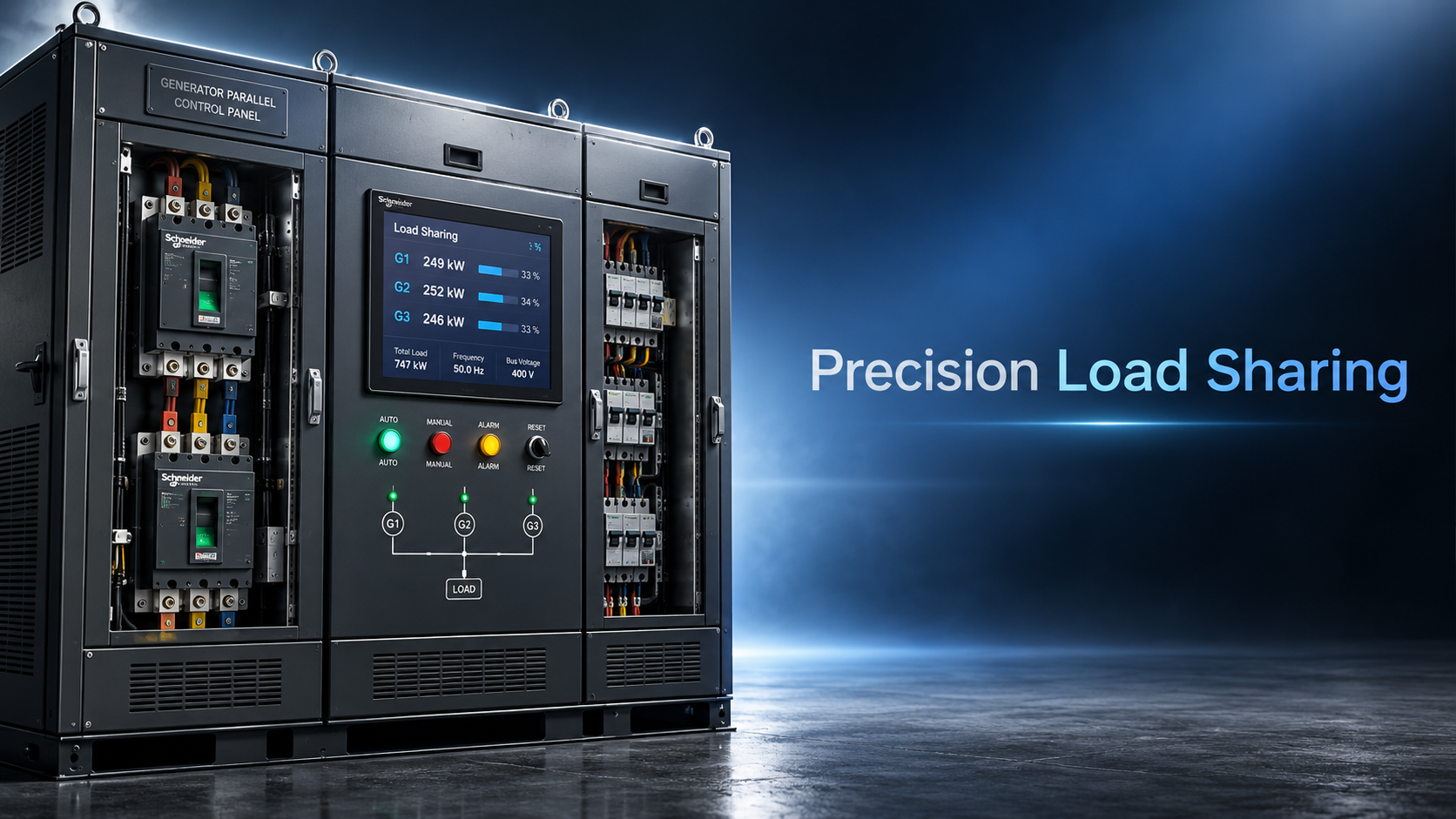
The Core Mechanics of Load Sharing in Parallel Systems
Mastering load distribution is critical for maximizing efficiency and reliability in an industrial generator set parallel operation setup. For technical evaluators and system engineers, improper load-sharing can lead to damaging circulating currents, uneven mechanical wear, and unexpected system failures. This comprehensive guide explores proven strategies and advanced controller configurations to ensure seamless power synchronization, helping you optimize your backup power infrastructure for demanding applications like data centers and heavy industries.
When multiple generator sets are synchronized to a common bus, the primary objective is to ensure that each unit contributes its fair share of both active (kW) and reactive (kVAR) power. However, achieving this balance is rarely as simple as setting identical parameters across all controllers. The physical and electrical characteristics of each engine and alternator pair dictate how they respond to load changes.
Active power sharing is primarily governed by the engine governor's response to frequency changes, while reactive power sharing is controlled by the alternator's automatic voltage regulator (AVR) responding to voltage deviations. If the governor settings are slightly mismatched, one generator might take on the majority of the active load, leading to overloading, while another idles. This imbalance not only reduces fuel efficiency but also accelerates mechanical wear on the heavily loaded unit.
Controller Configurations and Droop Characteristics
To prevent generators from fighting each other, engineers rely on droop characteristics. A droop setting introduces an intentional, proportional decrease in speed (for active power) or voltage (for reactive power) as the load increases. Typically, a 3% to 5% droop is standard for industrial applications. This creates a stable operating window where multiple units can share the load without hunting or oscillating.
For technical evaluators, understanding the difference between isochronous and droop modes is essential. In an isochronous setup, one master generator maintains exact frequency and voltage, while the others operate in droop mode to follow the master's lead. While this provides tight voltage and frequency regulation, it creates a single point of failure if the master unit trips. Conversely, a full droop system allows all units to share the load equally without a master, offering higher redundancy but with slight variations in frequency and voltage under changing loads. The choice between these configurations often depends on the specific sensitivity of the connected equipment, such as the strict power quality requirements in a Tier III data center versus the more forgiving environment of a mining operation.
Beyond basic droop settings, the proportional-integral-derivative (PID) gains within the digital controller dictate how aggressively the system corrects load imbalances. If the proportional gain is set too high, the system will react instantly to minor load fluctuations, causing the engine throttles to hunt and oscillate. Conversely, if the integral gain is too low, the system will take too long to stabilize the load sharing after a sudden step-load application, such as when a large HVAC compressor starts in a commercial building. Tuning these PID parameters requires a deep understanding of the specific engine's fuel system response time. An electronically controlled common-rail engine will react much faster than a mechanical pump system, necessitating different controller tuning profiles to prevent the faster unit from absorbing all the transient load.
Managing Circulating Currents and Reactive Power
One of the most common technical challenges in an industrial generator set parallel operation setup is the emergence of circulating currents. This occurs when the terminal voltages of the paralleled alternators are not perfectly matched in magnitude, phase angle, or waveform. Even a minor discrepancy can cause a significant current to flow between the units, rather than out to the load. This current does no useful work but generates excessive heat, potentially damaging the alternator windings and tripping protective relays.
Reactive power sharing is particularly sensitive to these discrepancies. If the AVR gain settings are not carefully calibrated, one alternator might excite heavily to supply reactive power, while the other under-excites, leading to a leading power factor condition that can destabilize the system. Cross-current compensation or reactive droop compensation techniques are often employed in the controller logic to force the units to share kVAR proportionally to their ratings. Evaluators must ensure that the controllers specified for the project have the necessary algorithms to handle these cross-current corrections seamlessly.
The complexity of load sharing increases significantly when the facility introduces non-linear loads, such as variable frequency drives or large UPS systems common in data centers. These loads generate harmonic currents that can distort the voltage waveform. If the alternators are not properly sized or if their impedance characteristics are mismatched, the harmonic currents will not be shared proportionally. One generator might end up supplying the majority of the harmonic currents, leading to localized overheating in the stator windings. Evaluators must ensure that the alternators selected are equipped with appropriate pitch and chording to mitigate harmonic distortion, and that the controllers are capable of filtering out these harmonics when calculating the fundamental reactive power sharing.
Practical Considerations for System Integration
Integrating these electrical theories into a physical system requires careful attention to the mechanical and hardware components. When designing a 20-3000KW diesel generator set configuration for critical facilities like hospitals or factories, the physical layout and cabling play a massive role. Unequal cable lengths or differing cable sizes between the generators and the common busbar can introduce varying impedance. This impedance mismatch alters the voltage drop seen by each unit's AVR, effectively ruining the reactive power sharing. Technical specifications must explicitly mandate symmetrical cabling and strictly defined busbar arrangements to mitigate these physical variables.
This level of integration is where the expertise of a source manufacturer becomes critical. At Guangdong Yundong Diesel Generator (EPOWER), engineering teams routinely configure parallel systems utilizing diverse power sources. When clients request a mixed fleet approach—perhaps combining robust Weichai or Yuchai engines for base load with high-efficiency Cummins, Perkins, or Mercedes Benz units for peak shaving—the control architecture must be meticulously designed. The physical footprint, cooling requirements, and exhaust routing for open or silent type enclosures must also be calculated to ensure that ambient temperature variations do not disproportionately affect one unit's derating, which would subsequently skew the load sharing. Providing these customized, one-stop power supply solutions requires looking beyond the generator nameplate and evaluating the entire operational environment, whether it involves high-voltage setups or integrating energy storage power equipment.
Commissioning and Ongoing Monitoring
A theoretically perfect design can still fail if the commissioning process is rushed. Load sharing must be verified at multiple load steps—typically 25%, 50%, 75%, and 100% of the total connected load. During this phase, engineers monitor the kW and kVAR readouts on each generator's control panel. A variance of more than 5% to 10% between units at any given load step indicates a calibration issue that must be resolved before the system is handed over.
During the commissioning phase, utilizing a dedicated resistive load bank is non-negotiable for verifying active power sharing, but testing reactive power sharing requires either a reactive load bank or a carefully controlled induction motor starting sequence. Furthermore, thermal imaging should be employed during these load steps to check for hotspots in the busbar connections and circuit breaker terminals. Unequal load sharing often manifests as uneven thermal distribution across the parallel bus connections. If a technical evaluator is reviewing a commissioning report, they should look for documented evidence of these thermal scans, alongside the digital controller logs showing the deviation percentages at each load step.
Furthermore, modern setups require continuous monitoring. Integrating the generator controllers with a remote monitoring system allows facility managers to track load distribution trends over time. If a specific unit consistently takes on 60% of the load in a three-unit parallel bank, the monitoring system will flag this anomaly long before a mechanical failure occurs. This proactive approach is a standard requirement for customized export projects where local maintenance teams need clear, data-driven diagnostics to maintain the infrastructure.
Navigating Standards and Compliance
Technical evaluators must also ensure that the parallel operation setup complies with relevant international standards, such as ISO 8528 for reciprocating internal combustion engine driven alternating current generating sets. These standards define the performance classes for voltage and frequency deviations during transient and steady-state conditions. While the standard provides the baseline, specific applications often require adherence to stricter guidelines, such as Uptime Institute Tier standards or local grid codes if the generators are intended for peak shaving or grid support.
Selecting the right components must align with these compliance requirements. For example, high-voltage generator setups reduce current and allow for smaller cabling, but they demand specialized switchgear and protection relays that do not interfere with the generator controller's load-sharing logic. Evaluators should work closely with manufacturers who understand both the electrical nuances of parallel operation and the regulatory landscape of the target market, ensuring that systems featuring Mitsubishi, Scania, or other brand units meet all local export and operational certifications.
Handling load-sharing in a parallel generator setup is a multidisciplinary challenge that bridges electrical engineering, mechanical dynamics, and control systems logic. There is no universal plug-and-play solution. The reliability of the system depends on meticulous parameter configuration, symmetrical physical installation, and rigorous commissioning. For technical professionals evaluating backup power infrastructure, focusing on these foundational elements ensures that the generator array will perform predictably and efficiently when the grid fails.
Specialized field of steel wire ropes
24/7 before-sales and after-sales services
Comprehensive technical support